
October 03, 2014
Rascal 2 prototype: first look
There's been radio silence over here at Rascal Micro headquarters for the last few months because of three all-consuming projects:
-
The new design for the Rascal 2.
-
A radiation monitoring system for a lab at the University of Texas.
-
My wife and I have a rather young daughter. It is amazing how having a kid plays havoc with your existence. Yes, I would do it again.
Anyway, due to said havoc, I'll get to the point. The first revision of the Rascal 2 is done. Unfortunately, I accidentally rotated two of the connectors by 180 degrees, so when the system is plugged together, the power supply is shorted.
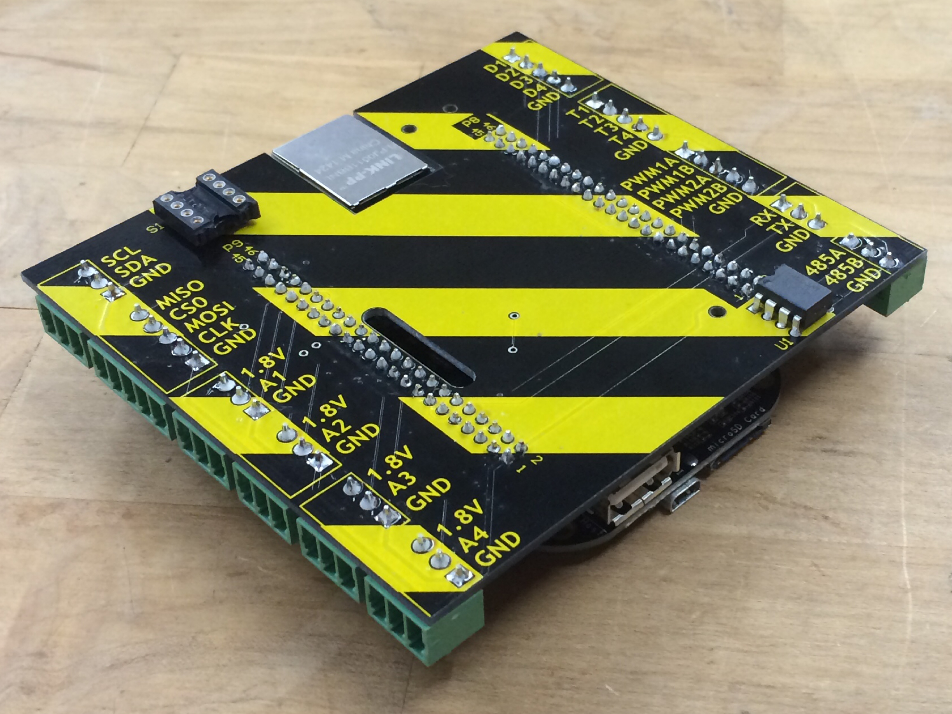
The picture above just shows one Rascal 2 PCB with the Rascal 2 brain (a Beaglebone Black loaded with the Rascal software) plugged underneath. There is still another PCB, yet to be designed, that will live under the brain and provide the Arduino headers familiar from the original Rascal.
I have a list of fixes and improvements for the Rascal, but the new PCB may take a while because of the radiation monitoring project I'm working on for the University of Texas (basically, setting a radiation sensor up with a modified Rascal, GPS, and wifi connection) I'd say more, but it's all secret for now. Also, I'm biking home to take the kid to the pool now. Zoom!
May 01, 2014
First iteration of OSHW stencil printer complete
(Background: I'm building a manual stencil printer for applying solder paste to circuit boards. The hardware design will be open source. There are more details in the first post about my stencil printer.)
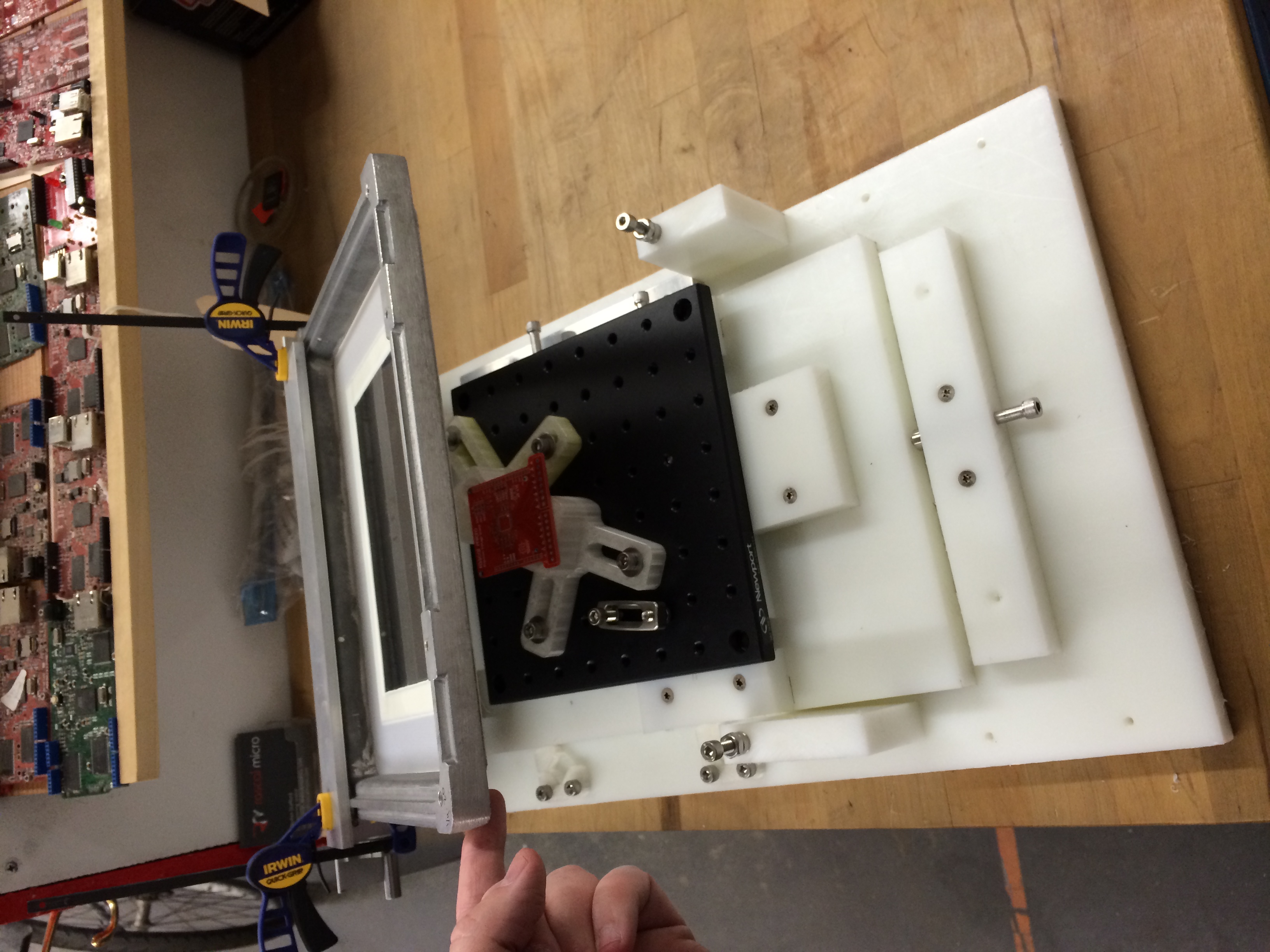
After a couple of failed mechanism designs, the first working iteration of my open source hardware stencil printer is complete. The stage can adjust the PCB position in X, Y and rotation while allowing no detectable backlash. Here's the system with the frame and PCB in place.
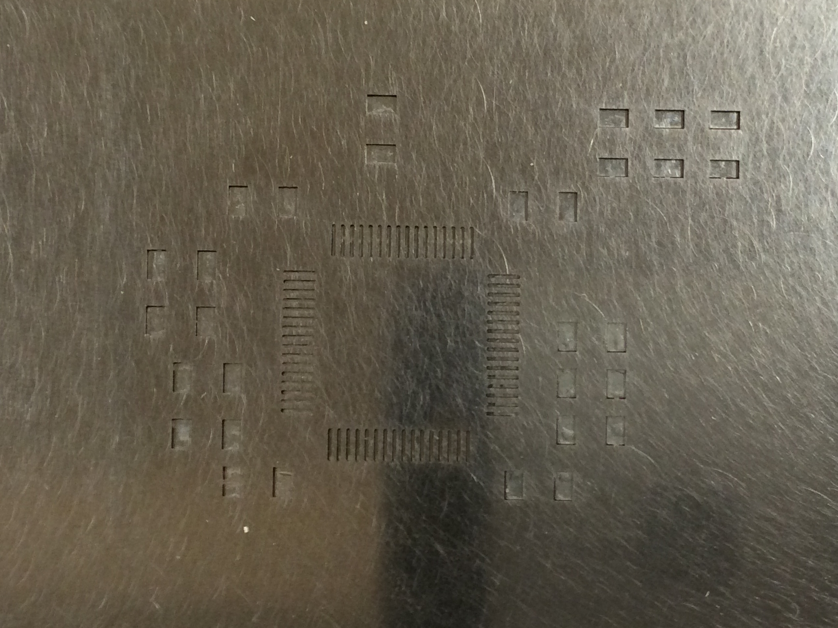
Here's a close-up of the stencil lining up with the pads of the PCB. You'll notice that very little of the red PCB is visible, which is a good sign, as it means that when I squeegee solder paste through the stencil, it will land on pads rather than the bordering regions of PCB.
What went right
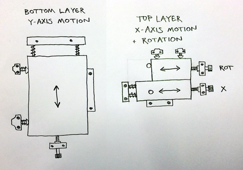
The low-backlash positioning mechanisms I made worked surprisingly well. The basic mechanism was a plate of high-density polyethylene (HDPE) that slid on dowel pins encircled by compression springs. A 1/4-20 socket head cap screw threaded into a PEM insert forces the HDPE plate to slide along the dowel pins, while the springs oppose that motion, eliminating backlash. This is how I built the X and Y stages.
The rotation mechanism was similar, but instead of two sliding dowel pins, it used a spring in tension that pulled a shoulder bolt against a small HDPE plate, which was adjusted by a 1/4-20 bolt like the other stages. Rotation required the different implementation to translate the linear motion of the bolt to rotation.
Here's a diagram of the mechanisms.
The hinge that holds the stencil clamp used a ground 3/8" shaft that connected bearings in pillow blocks to shaft mounts. I was not able to detect play between the bearings and the shaft.
The optical plate and locating pillars worked well. The plate was the most expensive single component, but it added a lot of flexibility to the system, and it looks cool.
What went wrong
Plenty went wrong with this iteration. Here's a list, plus a few ideas about what I'll fix when I iterate again. This iteration seems workable, but there are some bits that are a bit finicky. I'll probably use it now, and then rebuild it better when it breaks.
-
On the X stage, the dowel pins don't slide smoothly. This is because when I expanded the holes, I used a hand drill rather than a drill press, and I misaligned the holes. In realigning them, I gouged up the sides of the holes. Stupid.
-
The 1/4-20 threads are a bit coarse. #10-32 bolts would give 60% better resolution, so I'll probably use those instead. The bolt heads are also hard to turn by hand, so I should add some knobs, like these thumb screw knobs.
-
The shaft collars that I used to keep the stencil clamp from sliding sideways on the hinge shaft were too loose. They were machined pieces of HDPE pressed on the shaft. They provided a little lateral resistance, but not enough. I'll replace them with split shaft collars and space them off the bearings with some 3/8" washers. (Vic convinced me to use HDPE collars in the first place. Sorry, Vic!)
-
The stencil clamps failed utterly. I designed them to clamp the frame against the U-channel from below. The clamping worked great, but the clamp knobs were hard to reach and banged into everything. C-clamps that pinch the edges of the stencil are cheap, easier to set up, and more adaptable to different stencils. They win in every way.
-
The locating pillars worked well, but the design can be simplified. The slotted arms don't work very well for positioning. I'll redesign them so they can work with Newport's BC-5 base clamps.
-
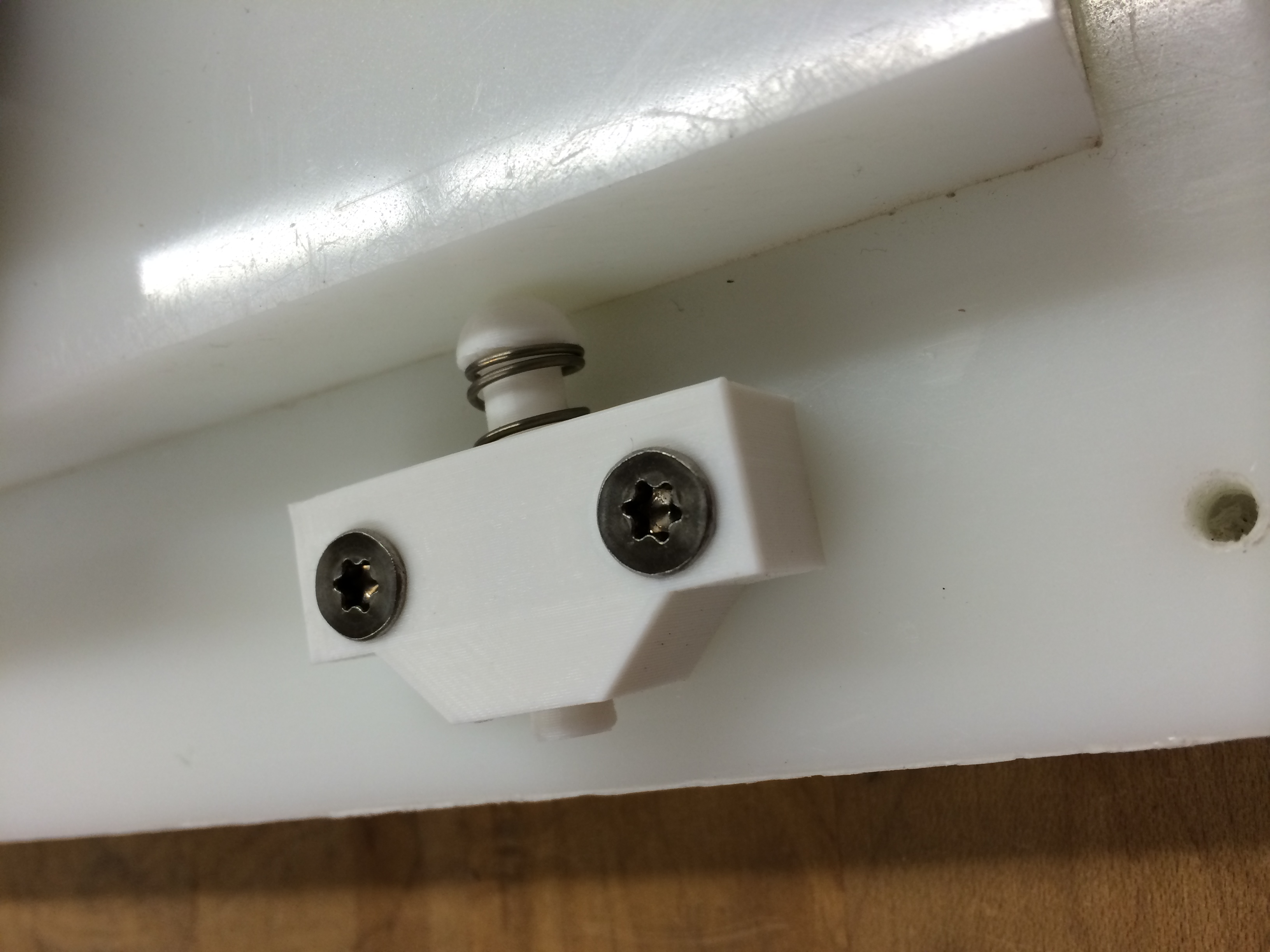
The 3D-printed flexures that guide the stages worked, but I fear they won't be durable. One of them cracked while I was playing with it. Their deflection range is barely adequate, and I suspect they will creep over time. I made a revised version that uses a spring-loaded plunger. The springs are the same as those used on the stage slides. Here's the improved version (also 3D-printed).
What happens next
Next week, I'll use the printer to assemble some Precision Voltage Shields. I'll probably also make a few easy upgrades-- the shaft collars and knobs mentioned above. I may also print modified locating pillars.
If you're interested . . .
If you've made it this far and are interested in more details, send me an email: brandon@ the domain of this blog. If I get a few emails, I'll document construction in more detail.
April 16, 2014
Stenciling PCBs on my desk
I try to assemble as many Rascal Micro products as I can myself here in Somerville. The Rascal itself has a ball-grid array processor, which is really hard to assemble reliably by hand, but simpler stuff I can handle.
For my Precision Voltage Shield, I assembled the first one by hand with a fine-tipped soldering iron and a microscope. The board worked great, but the process was stressful because I feared accidentally bridging the fine-pitch pins on the A/D converter. On the first board, I did actually bridge a few, but I was able to fix it up with solder braid. It was nerve-wracking.
Once I validated the shield's design by testing the first board, I ordered a laser-cut Kapton stencil from Ohara Rapid Prototyping. This let me run a typical surface-mount solder process: squeegee solder paste onto each shield, place the components on the shield with tweezers, and run them the shields through an oven to melt and then resolidify the solder.
The Kapton stencil worked well, but the setup was fiddly. I found it hard to keep the stencil aligned as I swapped in multiple PCBs. Part of this was because Kapton and tape are flexible materials. The way I aligned the PCBs referenced the edge of the PCB, which wasn't very repeatable as some of my PCBs have fuzzy edges from where they were snapped out of panels.
The standard industrial solution to this is a big machine called a stencil printer. A used one off Ebay would cost around $5000, or maybe $15,000 new. The next step down is a manual jig that costs around $1300. There are also cheaper versions in the neighborhood of $400, but those use the same "taped-down PCBs" mounting method that was giving me trouble before. The description of the positioning method sounds like it's just pairs of opposing clamps, which also put me off. If I didn't love building precision jigs, I would probably buy the $1375 STP-350.
Building an open source hardware stencil printer
Instead, I'm building a manual, open source hardware stencil printer. My hope is that I'll be able to sufficiently document a design that someone with access to a 3D printer, a tablesaw, and a drill press, plus some pre-made parts from a couple industrial suppliers, will be able to build a functioning printer. I've built the beginning of my printer, and while I can already imagine things that I would change in a subsequent revision, I think that it will work. The picture below shows an overview of the current design.

The thumbscrews in the back will clamp a stencil that can pivot up and down on the shaft that you can see poking out from behind the aluminum U-channel. The shaft is precision ground and slips into bearings that are pressed into pre-made pillow blocks. It's essentially a hinge that will force the stencil to return to the same place every time it is lowered. (I got my first stencil from Stencils Unlimited, but it's too early to tell whether it will work. It sure looks good.)
The black optical breadboard will be mounted on top of a two-layer stage for positioning. The bottom layer positions the PCB in one direction; the upper layer takes care of the other direction plus rotation.
The key requirement of the printer is that it positions the PCB with no detectable backlash, i.e. if you try to wiggle the PCB gently with your finger, it should not move.
The two pictures below show pre-made locating pins embedded in 3D printed parts. The locating pins are designed to fit snugly in a 1/8" hole, which is convenient because that size hole also accommodates both #4-40 and M3 bolts. The 3D printed parts are reasonably precise, but it doesn't matter if they're off a little bit, because you can just loosen the cap screws that hold them in place and reposition them. This is also designed to be adjustable for PCBs of various different sizes.


So now we have the PCB held rigidly; we just need to position it under the stencil with an adjustable mechanism that doesn't introduce backlash. You can see the beginning of the Y-axis positioning in the three springs in the first picture above. My plan is to oppose those springs with a fine-pitch bolt so that cranking the bolt in and out moves the platform in and out, with the spring taking out all the backlash.
In the long run, the documentation for the project will live on the OSHW stencil printer page.
(And yes, I should be working on the Rascal 2, but people keep ordering Precision Voltage Shields, so I have to keep building them, and the fiddly stencilling is killing me!)
March 31, 2014
Announcing Rascal 2
The Rascal has been a steady seller over the last 2 years, but it's time for a hardware upgrade!
Same philosophy, more reach
When I designed the original Rascal in 2010-11, the explosion of small ARM Linux boards (Raspberry Pi, Beaglebone, and the like) hadn't happened yet, and there were no Linux boards available with Arduino headers (except, briefly, a version of the late Chumby Hacker Board). To make an Arduino-compatible Linux board with a Python web interface out of the box, I had to build my own hardware. As a bootstrapped company, I couldn't afford to add any hardware capabilities beyond the most basic functionality.
Now, with small ARM Linux boards widely available, I can take the next step, which is to expand the capabilities of the Rascal by integrating sensors and motor driver circuitry. The goal, as has always been the case, is to make a small computer that makes an artist or scientist productive within a few minutes of taking the Rascal out of the box.
With the original Rascal, you got to skip the painful part where you wrestle with the Linux kernel and try to figure out how to cross-compile software for an ARM processor. With the Rascal 2, you will also get to skip the step where making the board talk to simple sensors drives you insane.
The Rascal 2 will probably run on top of one of the small ARM Linux platforms (probably the Beaglebone Black), which will mean better performance (2x the speed and 5-10x the RAM) at a lower price. The new Rascal will run the same software as the original with minimal changes under the hood to accommodate the new hardware.

New hardware features
The biggest change is that the Rascal 2 will come with a suite of sensors and motor drivers out of the box, so that you don't have to worry about figuring out how to make basic circuits work with the Rascal. The first prototypes of Rascal 2 will have four sensors: temperature, light, sound, and motion.
I might also add a few other hardware goodies to the Rascal: maybe an RS-485 transceiver or a connector for the Adafruit Neopixel LED strips. There may also be a higher-end version that will have an Arduino onboard to act as a real-time coprocessor, but that definitely won't be in the first release.
New software features
The first step is to get the current software working on new hardware (well, first I need to design the new hardware). After that, the next big upgrade to the software will be to get websockets working with the onboard sensors out of the box, so that you can see a real-time graph of all the sensors' output in your web browser without writing any code at all.
$50 off original Rascals until they're gone
The original Rascal is still available in the Rascal store, now $50 off, for the next month or until the current batch is gone. There might be another batch if Rascal 2 takes me a while to build, but don't risk missing out forever on the original Rascal!
older postsnewer posts